I have checked out all the mods, UP bushmans, schmidt brothers and the Yamaha version. I have no idea why this is not for sale in the US. Alas, I gave up and ordered a Canadian one shipped to my glass supplier so they can bring it to me on the down low.
Phazer upgrade
I have seen these installed but loosen up. By the looks of them, they have the ability to be welded to the crank side as it looks to be steel. This would stop the future slop. I will post back here once I get them in a couple weeks. I have also ordered the 4 wheeler style inner tie rods as my inners are shot.
If anyone has found a place to buy this in the US, please post.
Last edited:


Mooseman
I'm not all knowing. Post your question in forum.
- Joined
- Nov 3, 2009
- Messages
- 3,944
- Location
- Greely, Ontario
- Country
- Canada
- Snowmobile
- '07 Venture MP (gone)
'07 Phazer FX (gone)
'09 Phazer GT (gone)
'10 RS Venture GT (My current ride)
'10 Nytro FX (son's)
- LOCATION
- Greely, ON Canada
IIRC, it originated in Europe. There might be a disconnect between Yamaha US and the rest of the world, like when the MP was available everywhere except the US for the first few years.
You weren't able to get UP Bushman's kit?
You weren't able to get UP Bushman's kit?
MikeWalters
TY 4 Stroke Master
I have that kit sorry to say it was useless. Still tons of slop. If you figure out a way to modify it let us know.
I plan on welding it to the arm. Is that where your slop is? I noticed in a video someone posted, I could see alot of movement there. This would lock the bearing in.
turbogts22
Pro
- Joined
- Jan 16, 2021
- Messages
- 136
- Location
- Spooner, Wisconsin
- Country
- USA
- Snowmobile
- Two 2010 Phazer GT's
The whole design of that steering rack is the problem. You can make the bushings fit really snug to reduce slop but then you introduce too much friction making the steering more difficult. It all wears in after awhile but then ends up loose again. I ended up modding both of mine with needle bearings sourced from some extra steering pivots (the triangle shaped piece). This completely eliminated all slop in that area without adding any friction. Over 1,500 miles later they're both still tight and free of any slop.
IslandPhazer
Newbie
- Joined
- Jan 7, 2018
- Messages
- 15
- Age
- 26
- Location
- Manitoulin Island, ON
- Country
- Canada
- Snowmobile
- 2007 Yamaha Phazer Mountain Lite
+1 for this, I also spent about $800 (replaced essentially every steering component with OEM Yamaha Parts) and I still have about 1.5"- 2" of slop on the end of my bars. The kit mentioned was also installed and didn't make any noticeable difference.I have that kit sorry to say it was useless. Still tons of slop. If you figure out a way to modify it let us know.
matty k
Newbie
- Joined
- Nov 1, 2019
- Messages
- 24
- Age
- 40
- Location
- Kitchener ON
- Country
- Canada
- Snowmobile
- 2012 Phazer RTX, 1979 ET340, 1978 ET250
BeTheViper did you end up welding the bearing holders in place? Did it work out? That's what I'm thinking of doing because I had nice tight steering for about 200km after installing the "Heavy Duty Steering Bearing Kit" but now it's back to being loose and darting all over the trail. Which is what everyone said would happen. Oh well.I plan on welding it to the arm. Is that where your slop is? I noticed in a video someone posted, I could see alot of movement there. This would lock the bearing in.
So now my options are:
-Deal with it for the rest of the season & figure it out later,
-Weld the bearing holders in place,
-Epoxy them in place, (Loctite sleeve retainer? 2 part epoxy? JB Weld?)
-Order a UP Bushman Kit (might not come until the end of the season and I'm in Canada so it's going to be $$$)
I haven't opened up the machine yet to take a look but I'm sure that those bearing holders are just floating around in there. Someone tell me welding them is a stupid idea before I do it. (obviously I'm going to press the bearings out first)
turbogts22
Pro
- Joined
- Jan 16, 2021
- Messages
- 136
- Location
- Spooner, Wisconsin
- Country
- USA
- Snowmobile
- Two 2010 Phazer GT's
Welding the bearing holders could help. You'll need to see where the actual slop is though. The main problem I see with that design is that it only uses one bearing per side. Two bearings stacked would substantially reduce movement. That's how I designed my own steering fix using needle bearings and it's been flawless for over 2,000 miles.
matty k
Newbie
- Joined
- Nov 1, 2019
- Messages
- 24
- Age
- 40
- Location
- Kitchener ON
- Country
- Canada
- Snowmobile
- 2012 Phazer RTX, 1979 ET340, 1978 ET250
4 needle bearings? When you described using needle bearings I thought you would have used them inside the yoke piece in place of the plastic bushings. ("yoke"- the piece that the steering rods connect to, Yamaha Idler Arm 8GC-23826-00)Welding the bearing holders could help. You'll need to see where the actual slop is though. The main problem I see with that design is that it only uses one bearing per side. Two bearings stacked would substantially reduce movement. That's how I designed my own steering fix using needle bearings and it's been flawless for over 2,000 miles.
turbogts22
Pro
- Joined
- Jan 16, 2021
- Messages
- 136
- Location
- Spooner, Wisconsin
- Country
- USA
- Snowmobile
- Two 2010 Phazer GT's
4 needle bearings? When you described using needle bearings I thought you would have used them inside the yoke piece in place of the plastic bushings. ("yoke"- the piece that the steering rods connect to, Yamaha Idler Arm 8GC-23826-00)
https://ty4stroke.com/threads/phazer-needle-bearing-steering-upgrade.162378/#post-1553486
matty k
Newbie
- Joined
- Nov 1, 2019
- Messages
- 24
- Age
- 40
- Location
- Kitchener ON
- Country
- Canada
- Snowmobile
- 2012 Phazer RTX, 1979 ET340, 1978 ET250
It's been a while since I have contributed. I'll try to make this useful.
I do like the above link to the needle bearing conversion other than it is a tad out of reach of most.
This yamaha upgrade is great but for one thing. They sell it as a bolt on it is not going to stay in place for long.
Before I ordered it, I made sure my drag links were steel. They are and so the pieces can be welded in.
For better weld, see someone else with the patience to grind all the galvanizing off first.
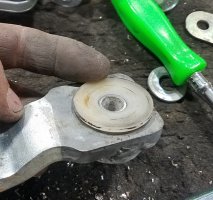
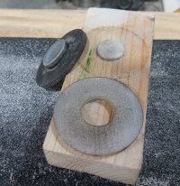
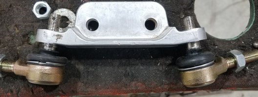
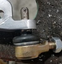
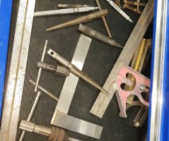
First, obviously, disassembly. Now grind everything for welding. Install bearings and the original bushing. Use the old plastic thrust washer to take up the slack between the drag link and the steering arms. (see second picture) It is too thick. to get this the correct thickness, make up a block of wood with a plastic or wooden dowel the size of the center in the spacer. (see third picture) Then use this to sand the spacer starting on a piece of 80 grit glued to a flat something. It will take a few minutes. As you get close to the finish thickness, switch to 180 grit. This needs to be close because the bearing used is not designed for much side load. The tie rods push up and down as they are mounted at an angle. A close tolerance here will be one more rock in our foundation of tight, long lasting steering.
Now bolt it together, use a big washer against the bottom of the spacer so the collar is not being tightened into the aluminum. Assemble with grease, something light and waterproof, your not going back here again. I used Super Lube, silicone grease. Great product. Keep fine tuning till you get no slop and moves freely without resistance.
Now that that is done, disassemble one last time and paint.
Before final assembly, make a strap to tie the tops of the bolts together. This will insure the bolts will stay parallel to each other and not put that load on the aluminum drag link. (see first picture)
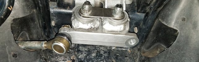
Also, this sits close to the motor, grind a taper on the motor side of the bearing cups. (see fourth picture)
I do like the above link to the needle bearing conversion other than it is a tad out of reach of most.
This yamaha upgrade is great but for one thing. They sell it as a bolt on it is not going to stay in place for long.
Before I ordered it, I made sure my drag links were steel. They are and so the pieces can be welded in.
For better weld, see someone else with the patience to grind all the galvanizing off first.
First, obviously, disassembly. Now grind everything for welding. Install bearings and the original bushing. Use the old plastic thrust washer to take up the slack between the drag link and the steering arms. (see second picture) It is too thick. to get this the correct thickness, make up a block of wood with a plastic or wooden dowel the size of the center in the spacer. (see third picture) Then use this to sand the spacer starting on a piece of 80 grit glued to a flat something. It will take a few minutes. As you get close to the finish thickness, switch to 180 grit. This needs to be close because the bearing used is not designed for much side load. The tie rods push up and down as they are mounted at an angle. A close tolerance here will be one more rock in our foundation of tight, long lasting steering.
Now bolt it together, use a big washer against the bottom of the spacer so the collar is not being tightened into the aluminum. Assemble with grease, something light and waterproof, your not going back here again. I used Super Lube, silicone grease. Great product. Keep fine tuning till you get no slop and moves freely without resistance.
Now that that is done, disassemble one last time and paint.
Before final assembly, make a strap to tie the tops of the bolts together. This will insure the bolts will stay parallel to each other and not put that load on the aluminum drag link. (see first picture)
Also, this sits close to the motor, grind a taper on the motor side of the bearing cups. (see fourth picture)
Attachments

Last edited:
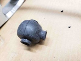
Now the inner tie rods. Found these on another thread. I bought aftermarket ones. They do not fit without work. BE WARNED
Since I own them, they are stronger, and have boots. The threads are the same. That is where it ends.
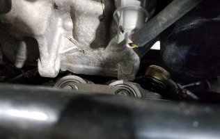
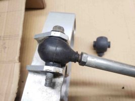
If you just bolt them on, it puts the centerline of the tie rod about 1/2in further back. This combined with the new larger head, makes a clearance issue with the motor around the lower hose. It catches on the clamp. (see first picture)
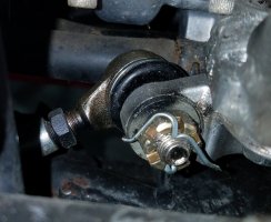
First problem to fix, the taper is further from the centerline of the ball. This makes the tie rod end and tie rode set further back from the drag link. (see second picture) About 1/4 inch. I used a taper ream.(see fourth picture) By continuing to ream and test fit I was able to move the rod end deeper into the drag link. (see third picture) This caused the threads to end too soon to tighten, so I used a washer on the back side. This got me down to about 1/4 in of centerline setback, that combined with the larger rod end is still touching the hose and clamp slightly. I need to pull it apart and get the rod end into the drag link further. I think I can go an 1/8 deeper safely. Then I am going to switch to a stainless band clamp on the hose. Those two things should give me safe clearance.
In the fifth picture, you can see on the left where I opened up the hole for the rod to move through. Compare this to the hole on the right. The rubber flap would also drag a little. I fixed this by removing the plastic push in, pulling the rubber with pliers and drilling a new hole in it. Reassemble with a new push in. Then trim any more excess rubber on the inside with a razor blade.
Since I own them, they are stronger, and have boots. The threads are the same. That is where it ends.
If you just bolt them on, it puts the centerline of the tie rod about 1/2in further back. This combined with the new larger head, makes a clearance issue with the motor around the lower hose. It catches on the clamp. (see first picture)
First problem to fix, the taper is further from the centerline of the ball. This makes the tie rod end and tie rode set further back from the drag link. (see second picture) About 1/4 inch. I used a taper ream.(see fourth picture) By continuing to ream and test fit I was able to move the rod end deeper into the drag link. (see third picture) This caused the threads to end too soon to tighten, so I used a washer on the back side. This got me down to about 1/4 in of centerline setback, that combined with the larger rod end is still touching the hose and clamp slightly. I need to pull it apart and get the rod end into the drag link further. I think I can go an 1/8 deeper safely. Then I am going to switch to a stainless band clamp on the hose. Those two things should give me safe clearance.
In the fifth picture, you can see on the left where I opened up the hole for the rod to move through. Compare this to the hole on the right. The rubber flap would also drag a little. I fixed this by removing the plastic push in, pulling the rubber with pliers and drilling a new hole in it. Reassemble with a new push in. Then trim any more excess rubber on the inside with a razor blade.
Attachments
Last edited:
turbogts22
Pro
- Joined
- Jan 16, 2021
- Messages
- 136
- Location
- Spooner, Wisconsin
- Country
- USA
- Snowmobile
- Two 2010 Phazer GT's
Good pics! That reminds me I need to swap over the inner tie rod ends to the ATV style this summer. I have them sitting in a box somewhere. I also bought rubber boots for the outers. Hoping to keep lube in and water out.
Attachments
Similar threads
- Replies
- 8
- Views
- 2K
- Replies
- 8
- Views
- 1K
- Replies
- 17
- Views
- 3K
- Replies
- 8
- Views
- 530
-
This site uses cookies to help personalise content, tailor your experience and to keep you logged in if you register.
By continuing to use this site, you are consenting to our use of cookies.